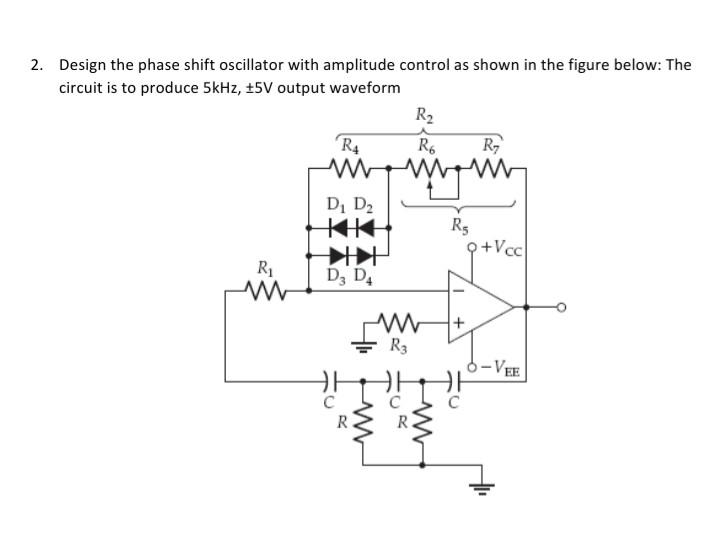
Solved 2 Design the phase shift oscillator with amplitude Circuit Diagram I assume you want to have a variable phase shift so as to adjust the subwoofer speaker output waveform to the output of your main speakers at the crossover frequency so they are in phase. That could likely be best handled by an all-pass filter, such a Dick posted (but a single-pole circuit should be sufficient since it can be adjusted for 0
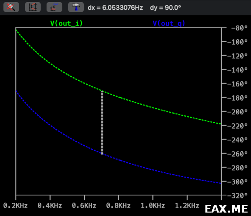
The overall phase shift is close to 360° across the audio band for circuit #1 (+180° at 20Hz and -180° at 20kHz). This is not audible. Circuit #2 has an overall phase shift of about 660° across the audio band, but this too is inaudible. See below for more info on the phase shift networks.
Project 204 Circuit Diagram
The Phase Shift Circuit Does This: Signal Source Input Output Three stage Phase Shift Network Note that each C-R section shifts the phase of the signal by 60 degrees. Thus the output is shifted by a total of 180 degrees with respect to the input. The frequency is 1050 Hz C20 = C21 = C22 = 0.022uF R20 = R21 = R22 = 3k Ohm

The timing differences cause a constantly changing phase-shift between the original signal and the duplicated signal(s). notches are formed at the frequencies where the all-pass circuits created phase-shifts. Phaser parameters in Nectar Pro While there are lots of unique-sounding audio effects for sound design, there are a few you're

alignment based method of designing multi Circuit Diagram
Phase shifters are important circuits in audio processing and communication systems, used for various purposes including audio equalization, signal mixing such as in SSB modulation, AM modulation and image processing. An all-pass filter is a special type of filter that allows all frequencies to pass through without attenuation, but alters the phase response of the signal. EE4435 Fall 2002 Design Project 3 A Phase Shifter Effects Box. Object. The object of this experiment is to design a phase shifter circuit for special effects audio signal processing. Background. Figure 1 shows a first-order all-pass filter with a JFET used as a variable resistor to control the pole and zero time constants in the filter transfer A phase shifter circuit is an electronic circuit that is used to shift the phase of a signal without changing its amplitude. It is a fundamental component in many signal processing systems and is used in applications such as audio processing, frequency synthesis, and phase modulation, AM modulation and demodulation, SSB modulation. There are several ways to build a phase shifter circuit, but